Deluge MIDI Host Mod Buildlog
 iFreilicht
GermanyPosts: 39
iFreilicht
GermanyPosts: 39
Current status

Looks awesome, right? Unfortunately, it doesn't quite work. It did, sometimes, if I was lucky, but there were too big issues:
- The whole thing doesn't boot when powered by USB, only when powered by batteries, so no host device could be connected
- RK 005 doesn't connect to hub most of the time and detects no devices, so the hub only outputs power. Lame.
Actual current status
The 555 timer board will power the RK005 after everything else, which for some reason makes it more reliably detect the downstream devices.
So, it's still a work in progress.
Original post
Hi everyone! Bought my deluge a week ago, huge fan, such a powerful and fun device. It's replacing the OP-Z for me, which was much more portable and great fun as well, but ultimately not the right fit for a bunch of reasons.
While the Deluge is more powerful than the OP-Z in a lot of ways, one feature I'm missing quite a bit is the ability to act as a MIDI host. Mind you, it was terribly buggy on the OP-Z (like a lot of things right now), but it was very convenient to just connect a Keystep with just one cable and be ready to go.
So, that's what I will mod into the Deluge. Specifically:
Important Features
- MIDI Host with 4 USB ports - Enable the Deluge to act as a host to MIDI devices
- Provide Power to MIDI devices - All connected USB MIDI devices will be provided with power from the internal battery/power bus
- MIDI thru between USB and DIN - Deluge can already do that (which is awesome, btw), but I need to keep that feature alive
Potential additional Features
- One more CV/Gate/Clock output - Can't have enough of those, can you?
- Battery level indicator - Self explanatory
- MIDI Status LED - Blinks on signal receive
- USB C input jack - I charge most of my stuff with USB C, so that would be a nice modernisation
- Increase battery life by up to 400% - Not sure on the exact number yet, will need to be tested.
How I'm going to achieve that?
Short Story
Put an RK 005, a USB Hub and a Powerbank into the Deluge, cut a few holes and solder it together right.
Long Story
Space
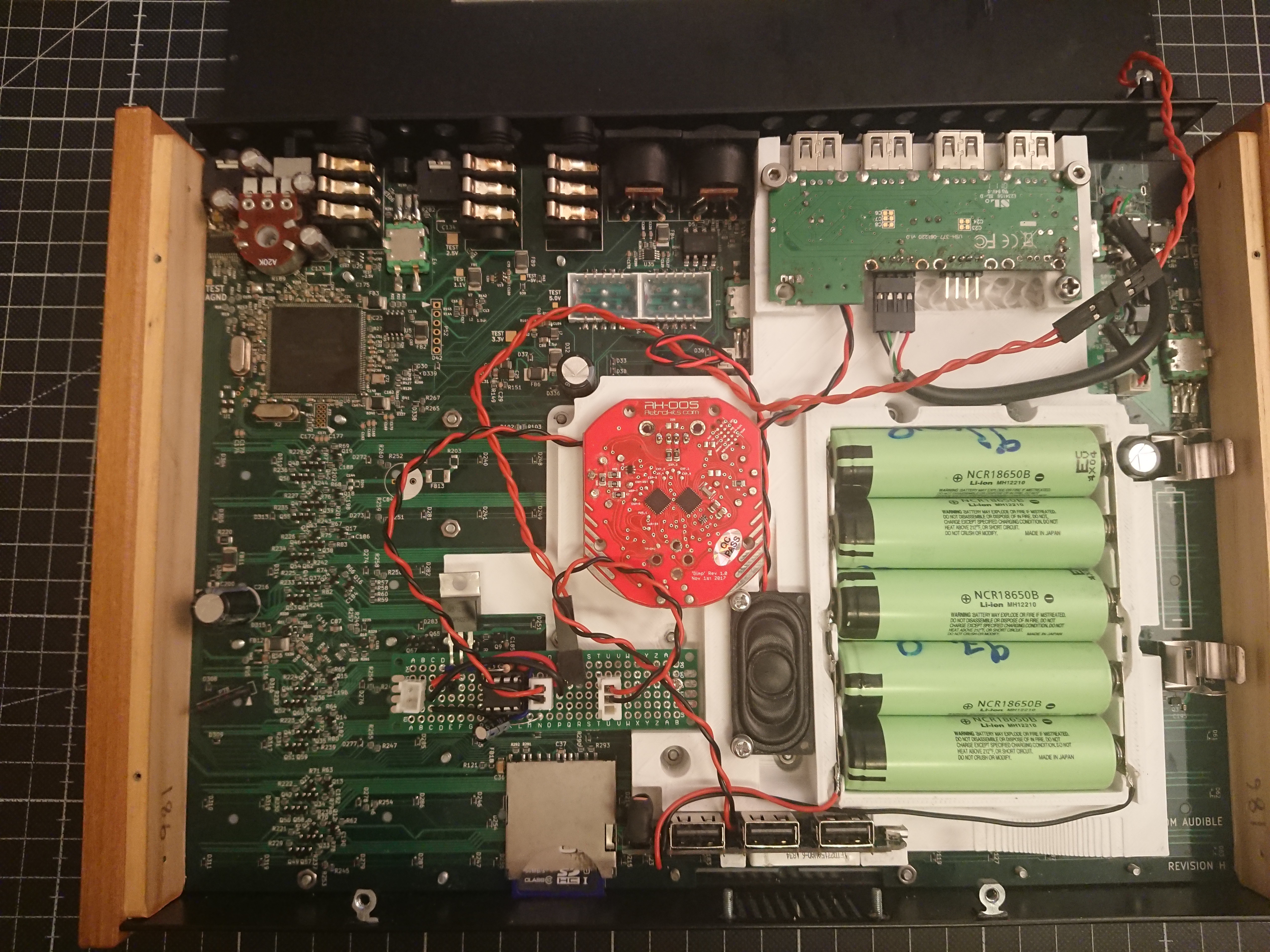
Here you can see what the Deluge looks like with the bottom panel removed. Lots of free space, about 21mm deep.
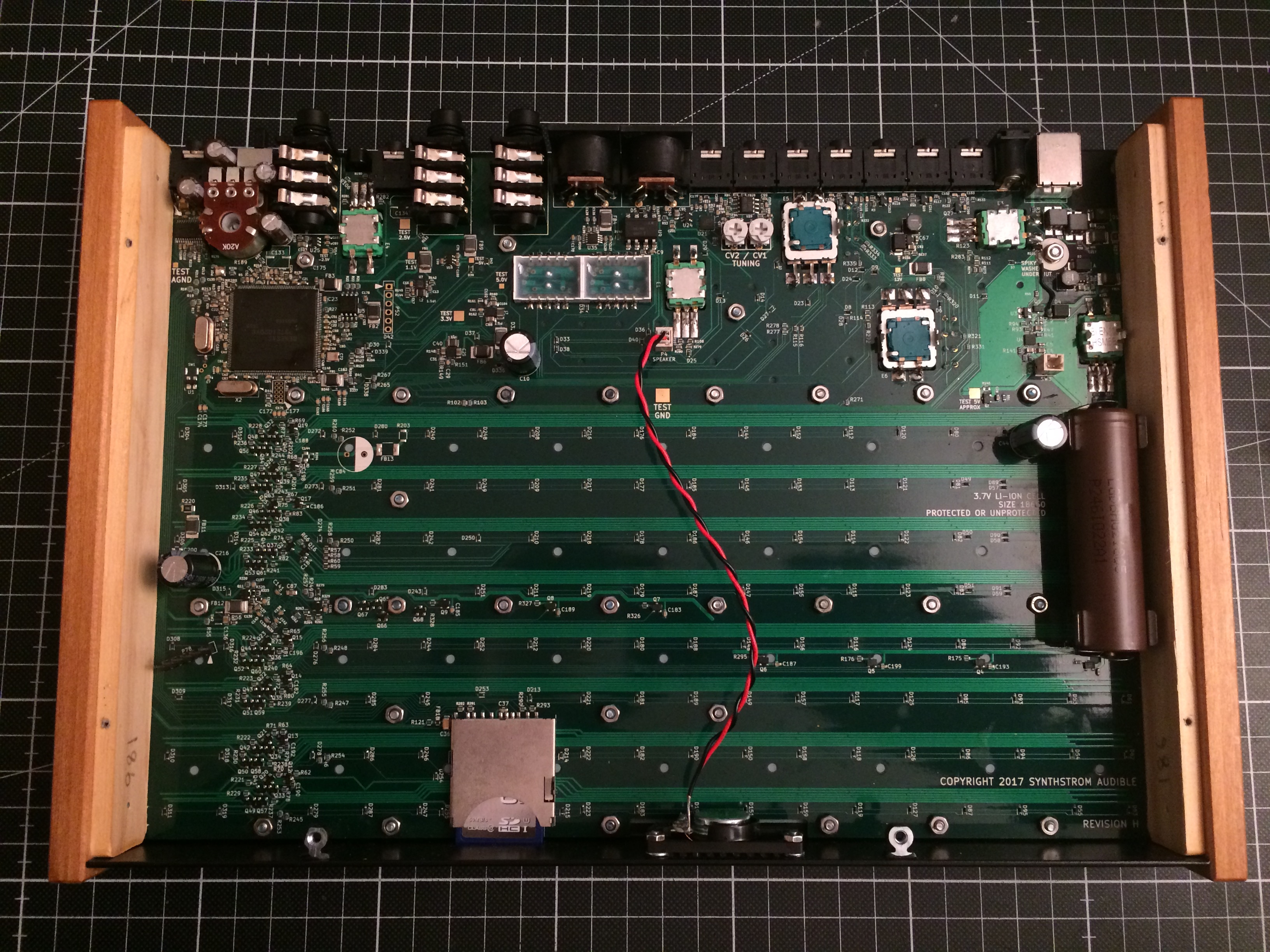
Into this free space I want to fit an RK 005, a USB Hub, and a Powerbank. All of those things will be held in place by 3D-printed mounts that will in turn be mounted to the deluge using Female-Female M2 Standoffs in place of some of the nuts you can see in the picture.
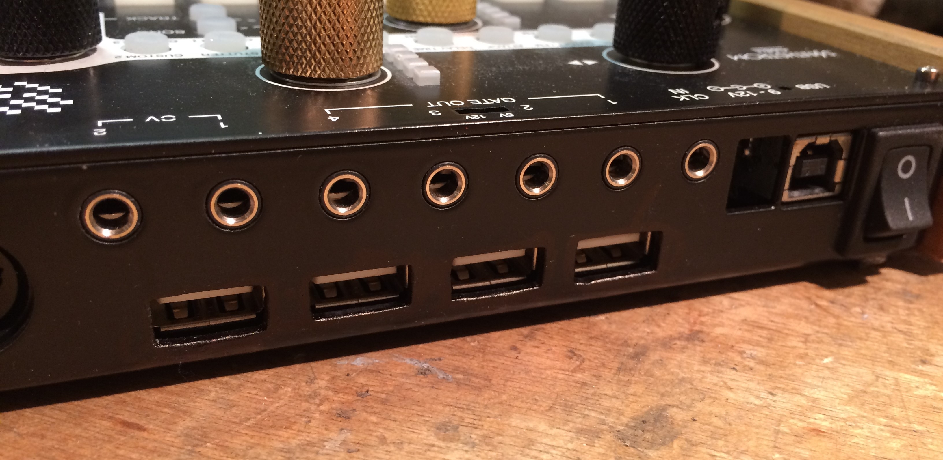
And here we have the rear connector area, as shown in the banner above. The 4 USB ports will be sitting underneath the CV/Gate outputs.
Components/Mods
Retrokits RK 005 is a Standalone USB MIDI Host and MIDI Interface. Any message it receives on an IN port will be echoed to all OUT ports, and if it's connected to a PC or other MIDI Host, will also be visible to that device. The cool thing, like a PC, it has full support for USB Hubs, so you can (in theory) connect up to 127 USB MIDI devices to it.
It also has a configurable TRS jack that can be configured to Gate, Clock or CV output and any combination of two of those, which I could put next to the USB ports.
And it has a status LED, which could be a useful thing to make visible as well.
To fit into the chassis of the Deluge, I will have to desolder the TRS jack and the DIN MIDI connectors. Luckily, as the Deluge has MIDI through between USB and DIN, I won't be needing those anyway.

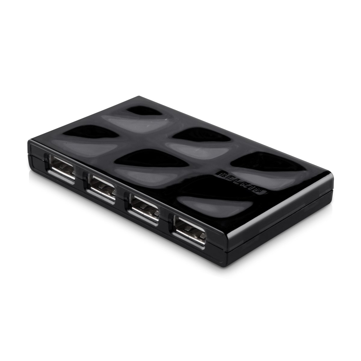
A 7-port USB 2.0 Hub. The flat form factor is important, as is the number of ports. Four of them will face outside, one of the ones facing inward will be connected to the deluges USB port. Then I still got two left for further mods. I'm thinking a Raspberry Pi Zero to interface with Bluetooth MIDI gear, for example.
The case of this will be removed, of course.
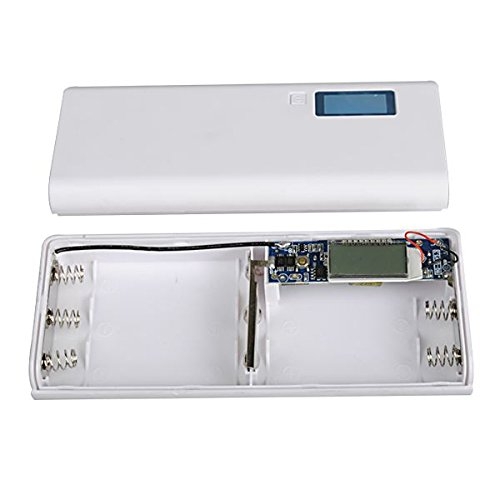
A 5x18650 powerbank kit (similar to what's shown in the picture). The case I don't care about, I only need the circuit. This will be connected to five 18650 batteries, the single one in the Deluge right now will be removed.
I'll probably solder the USB connections, plugging in cables in there feels to error-prone and unreliable.
If I want to make the battery indicator visisble, I'll have to desolder it as well.
Sidenote: I will not re-use the 18650 cell of the deluge. I'm getting five new ones from the same batch that will be matched by their inner resistance. This is important for the parallel charging and discharging to work properly.
The Deluge itself will also have to be modified. First of, the battery goes out. The battery holder and capacitor will be left in place unless I run out of space. The 9V input will be desoldered, as well as the USB B connector. In the place of the latter, I'll solder a cable connected to the hub, as shown below. If I'm lucky I can just re-use the USB connector by turning it upside down, that would be pretty smooth. The SW3 header (the one the power switch connects to) will be bridged so the Deluge turns on or off as the powerbank provides power or not. The power switch itself I'm not sure about. Whether I can reuse this depends on how the powerbank behaves exactly. And, of course, I will have to cut holes into the rear/bottom plate to expose the USB connectors.
For some additional indicators, like the MIDI and Battery LEDs, I could use the speaker grill. If I do that, I'll have to reseat the speaker and work out how to redirect the sound towards the grill again.
System Design
Here's the plan I threw together in paint.net (for the pedantic: Arrow direction represents logical USB downstream direction)
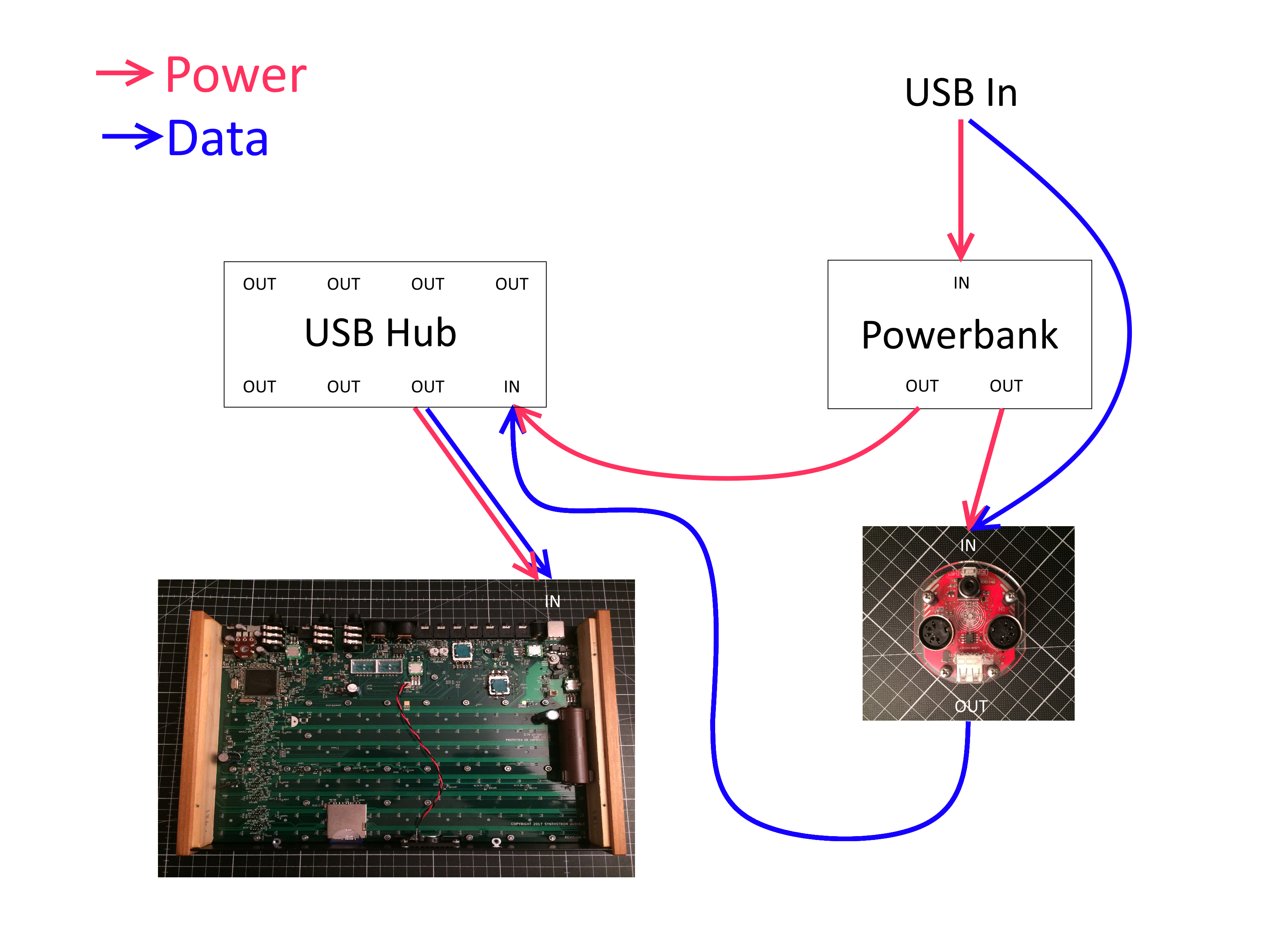
Really quite simple. The Powerbank has to be bypassed as powerbanks normally don't forward incoming data; instead, they connect the pins using a combination of resistors to communicate to the device being charged how much current it can pull.
And the RK 005 is bypassed for power to give more headroom for connected devices
The Beginning
Thanks for reading, hope you'll follow me on this journey. Maybe you have some ideas/tips as well? Feel free to share any thoughts!
Comments
Woohooo that sounds awesome!
Odo Sendaidokai from Berlin
Your warranty is now void.
Just kidding, awesome work! :P
Actually, I've been thinking about something like that, but with some additional microconteroller to "expand" the Deluge in a few ways not possible by firmware, but in terms of MIDI RK002 can process control signals as well IIRC.
Interesting idea.
Why not go straight for a Raspberry Pi, embedded in the side panel which doesn't have the battery in front of it? That could give you a more flexible solution to play with midi data and you would have midi bluetooth.
You are my hero, iFreilicht. I'm excited to see how this project goes.
Might I suggest the Klarus 18GT-36 as a good candidate for your 18650's. They are rated at 3600mAh and have top-notch protection circuitry.
It really do!
Haha this is the most expensive piece of gear I've modded so far, I am a little nervous
Yeah the RK 002 is awesome already, but AFAIK the firmware isn't open, so unless there's a firmware that already does what you need, maybe something like the Axoloti would fit your bill better?
I didn't even think of that! And when buying the RK 005, I didn't yet know the Deluge could do MIDI thru between USB and DIN, so I wanted it for that as well.
A Raspberry Pi Zero could do everything I want and is way cheaper than the RK 005, but it needs to boot, I have to install and piece together drivers and software and all that jazz for it to properly work. The RK 005 is a solid piece of gear and very reliable. But now that you've said it, I am really quite intrigued. I'll get one and see how easy it is to make it into a MIDI host/device. Looks like someone on these forums already did it as well.
You and me both, bud
Thanks, I already ordered some used Panasonic NCR18650Bs, though. Total of 19 bucks, the guy removed them from an E-Bike battery. Maybe I'll upgrade in the future, though > @OnoSendai said:
Ok so there is a problem with this. The Pi can only act as a host or a device, it can't do both at the same time. Strictly speaking, it only ever has to do one of the two at once, but switching between these two modes without physically plugging it over from the hubs input to its output isn't trivial.
One solution would be to have two raspberry pis, one acting as host, one as device, and letting them communicate via serial, but that seems excessive. This seems to be how things are done on the RK 005, though. They have two identical MCUs on there which seem to be Cortex M0+ based.
What I can see working is using an USB-to-Serial converter and have that represent the device side. The Raspberry pi can still host and just treats the serial connection like any other MIDI connection it's handling.
wow you are a genius @iFreilicht !
amazing, resoldering the power system.. i couldnt do that in my dreams 😀
hope rohan sees this. he could even do a new Deluge 2.0 Hardware “Host Version”. Same as the Deluge 1.0 but with your design plus an usb out for hooking up a Deluge 1.0. like Roland AIRA just better.
Thanks man, I appreciate it!
I mean, if things go well maybe there could be an add-on kinda thing? Let's see how this works out first
One thing I definitely learned to appreciate while planning this was how elegant and simple the hardware design of the Deluge is. It's just one big PCB, they used some tricks to make through-hole components surface mount to bring everything to the right level, it's super clever!
Update
Today I received the powerbank and batteries, did some functionality tests and started working on the general layout.
Parts received
Powerbank kit
I only need the PCB of this.
18650 cells
The seller matched them by inner resistance for me, which is important for non-balanced charging to work properly
About 3000 mAh each.
Function testing
Alright, so there's something very exciting I found out about the powerbank: It wakes up automatically once a device is connected. To test this, I connected the 5V and GND leads of an open USB cable with a 1.1k resistor (seemed like a safe value), you can see a video here.
This is very good, as it means I can reuse the original power switch on the Deluge, I only have to rewire it. It has to switch the power going out from the powerbank on and off and the behaviour will be exactly the same as it is with the deluge normally.
I also tried out the powerbank with all the cells, the RK 005 and a keystep, that worked flawlessly as expected.
Modding
Desoldering through-hole stuff is hard. Seriously, I wanted to desolder all the connectors from the RK 005, but after taking half an hour for just the TRS jack and ripping out all pads in the process, I decided to leave the MIDI connectors on and just trim their legs a little to give me more breathing room. It will fit like that, as shown further below.
Also, I got lucky with the ripped-off pads. All the connections I need are still accessible.
Same for the Powerbank PCB. I dismantled the powerbank and tried to desolder everything I wouldn't need. The battery leads were easy, they're just surface mounted, but the USB ports were impossible. The through-hole parts of those connectors connect to ground directly, sinking all the thermal energy into the PCB. I couldn't even get the solder to flow with these.
However, this is all fine. I can just solder cables to the exposed legs on the rear of the USB connectors, that's not hard.
Fitment and Layout
Exciting coincidence: The RK 005s Jack fits the cutout for 9V power perfectly. Guess the dedicated clock-out is going to be easier than I thought.
And here's the rough layout I'll be using.
I wanted to stack the batteries horizontally first, but the pitch between the mounting posts for the PCB doesn't allow for that. The USB hub will fit over the CV/Gate outputs as discussed, but hasn't arrived yet.
Here's a view of the battery level display behind the speaker grill. It's much easier to read with two eyes, still not perfect, but good enough to be usable.
And of course, the lid still fits:
Next steps
When the Hub gets here, I want to test the fitment of that as well.
Apart from that, now it's time to go into CAD and design the 3D printed mount for all these components.
Thanks for reading!
Update
Alright, today I crossed the point of no return: I desoldered the main USB and 9V connector, soldered a USB cable in its place and then resoldered the USB connector upside-down in the same spot.
First off, desoldering. Worked a lot better than on the RK 005. More patience, less material and higher surface area because of trimmed legs were some of the factors.
Here you can see the gap between the power switch and the PCB is big enough for the cable USB to fit through.
Below, the cable soldered, viewed from the top. To do this, I put the separate wires through the through holes without stripping them and just soldered from the bottom. This way, the isolation just melts away and the solder connections come out perfectly. Of course the room should be well-ventilated when doing this
Then I trimmed the ends of the wires off with a flush-trim cutter, now they stick out by maybe .5mm.
And finally, the solder points were covered with electrical tape, and the original connector was soldered back on upside-down to then become the new input for the powerbank and RK005.
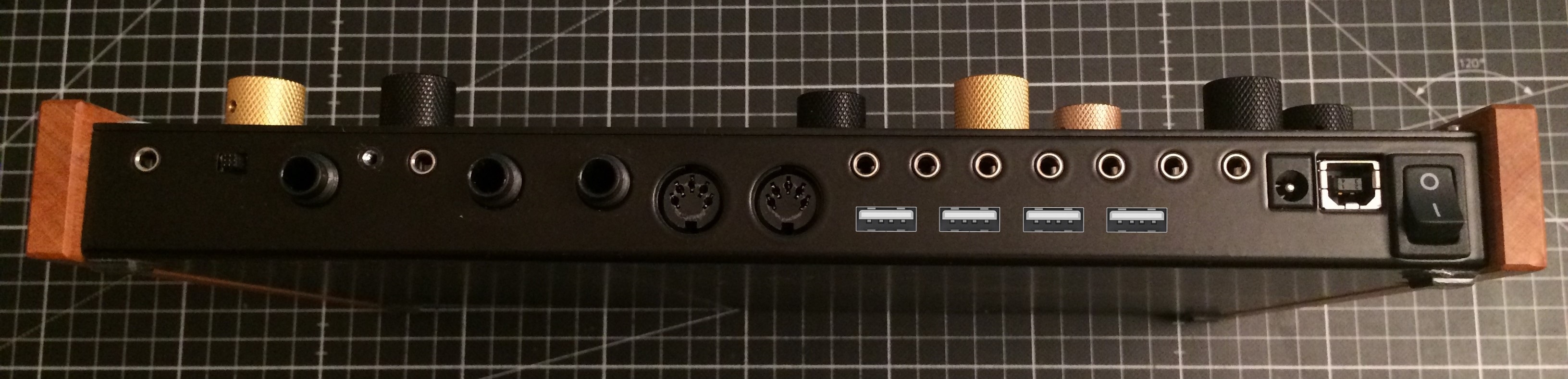
And this is how well that connector fits into the rear panel. Pretty much looks stock, which is pretty cool.
Updates left and right
All components are here now!
In addition to the RK 005 and all the powerbank stuff we've also got the RasPi Zero W (the W is for wireless, which means it has WiFi and Bluetooth onboard, which the original Zero didn't), and the USB Hub!
The hub
You can see that I already desoldered the internal downstream connectors of the hub and the power adapter jack.
I also had to remove two resistors from the hub to get a larger surface area when mounting them. The resistors were only used for debugging LEDs (which are not installed), so they served no purpose and the hub works fine without them.
Now comes the cool part. As I found out, the power adapter jack handles 5V perfectly fine, and it supplies all output ports with power directly (after some bypass caps and protection diodes). So I can connect the output of the power bank directly to the hub and use the maximum current it can provide.
Previously I thought I'd have to supply all internal devices directly from the powerbank to not overload the hub, but that seems to be no problem now. This means cabling will be simpler and less soldering will be required.
The main structure
Now the most important bit: In the last two days, I modelled the main structure that everything is mounted on. This is what it looks like on screen:
There's a lot of things going on here. First off, this structure is mounted directly to the PCB screw posts, which means there is a hole in the underside for every single component on the PCB. Measuring all of that out and then printing prototypes took the better part of a day, but on the second attempt, everything fit perfectly:
The main reason for this is the tight clearance between the batteries and the diodes on the PCB. If I were to lift the part up and try to save material that way, it wouldn't be strong enough to hold the batteries anymore. There are a few points where the compartments for components are so close that the wall thicknesses become too thin for my printer to print.
You may also notice that there are some tapped screw holes in there. I can not print the thread, as I'm printing at .3mm layer heights they are way too fine, but tap them into the plastic directly. I've done this a few times and it works really well and is surprisingly strong if the thread is long enough.
Now, we can get a better idea of how everything will actually be placed:
Next steps
So, this is printing now, will be done in like 7 hours.
Hopefully everything fits. If it does, I can then start to assemble everything. If not, maybe I can still salvage it. The walls are relatively thick, filing and drilling holes is no problem.
Once everything is in place, I can go on to modding the back panel and soldering everything together.
Thank you for attempting this and documenting it. Really enjoying the build process.
Some serious hacking there! Probably not much use to you now but these little midi USB hosts are pretty good http://www.hobbytronics.co.uk/usb-host-mini
Ah, I thought they could be great for transitioning to a RasPi-based host, but they only support one device, no hubs.
Thanks so much!
Boom, update!
Print went well, not much to report here. The first layer wasn't great, so some of the screw holes came out weirdly, but that's alright. I did a test print to see if I could print the "floating" section the hub mounts to with bridging (an experimental feature in cura), but it sagged too much. So in the end, I went for regular supports.
Fitting went OK. It seems I was sloppy when measuring the position of the MIDI ports, so I had to file off quite a bit off the left side of the hub section. I also cut off the rear support for the USB hub, as it prevented me from fitting cables there. You can see the infill pattern, which looks rather funky. Once that was done, the part fit into the deluge perfectly.
Now for test fitting all the parts. I really messed up the RK 005 mount, the screw holes don't go all the way through and are shifted up by 1-2mm. Luckily, the cutouts for the midi ports are also too close together, so it just clamps to the part without any screws. Apart from that, everything fit quite nicely.
And now the biggest jump; everything mounted and soldered together. I forgot to take many pictures along the way, but I'll walk through some of the challenges afterwards.
This took a hell of a long time. Mounting the battery holders was quite hard. I had to cut and file them a few times and some still had to be pressed in with the soldering iron so the plastic would melt and let them slid into place. Then I didn't leave a lot of room for soldering them together, so I had to hold the cable with pliers while soldering and feeding solder into the joint.
The power cabling was also quite a task. From the USB port, one cable goes to the powerbank, carrying only power, and one goes to the RK 005, carrying only data. The connector was not designed for having cables soldered to it directly, so after finally managing to get them on and making sure there were no shorts, I used hot snot to secure and isolate the leads.
However, the cable to the RK 005 also has to be connected to power coming from the powerbank, which needs to be switched together with power going to the USB hub. So, I soldered a female pin header to the 5V out of the powerbank on one lead and the Power in of the hub and 5V in of the RK 005 on the other lead, and soldered the GND of the RK 005 onto the GND going from powerbank to hub. Again stabilised with hotglue, and made to look nicer with heatshrink and tape. This was probably the hardest bit of soldering I've done in this mod.
When doing this, I also made sure to not build any ground loops. Ground now has the same path as power input, and only fans out like a tree to all the components.
Output soldering on the RK005 went smoothly, but desoldering was quite hard again. Not sure what it is with this board. You can also see the misaligned screw holes in this picture.
Little detail on the speaker: A reflex port. I didn't have space for a proper channel, unfortunately, but it was a fun feature to model
Another piece of the puzzle: The power switch bypass on the deluge.
And then, the final link in the chain; the spot where the deluge USB up is soldered to the hubs USB down port.
Now everything's connected properly and should work, right?
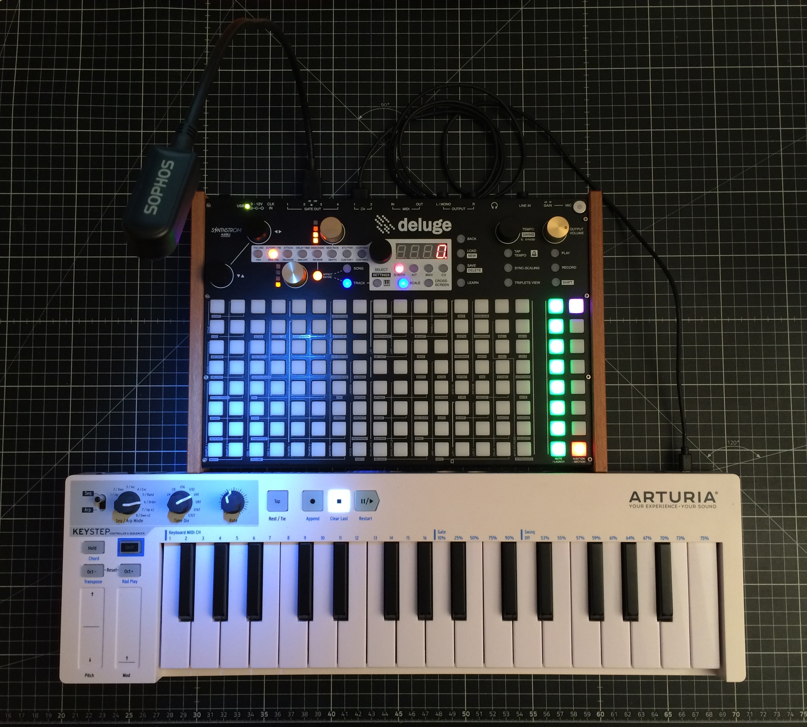
Damn right it does
The only difference you can tell right now is the battery indicator in the speaker grill.
Now, there are a few peculiarities that this mod brought with it. The smallest problem is that the USB LED now flashes between green and yellow, probably because there's no battery installed in the Deluges own battery holder.
But the bigger problem is that it doesn't work when plugged into USB power. With phone chargers, it seems to boot but none of the buttons work (and the led is red sometimes), and on PCs it refuses to boot altogether.
I suspect the powerbank doesn't like charging and putting out power at the same time. I'll have to investigate this.
Next steps
For once, I have to investigate the power issues mentioned above. Potentially, bypassing the powerbank with a diode could already solve this problem.
Another problem is that I already broke off the USB port after plugging in the cable for the 10th time or so, so I need to find a way to mount it more securely than just surface soldering it to the PCB.
Then cut holes into the rear panel to expose the USB ports, and we're done.
Thanks for reading!
Super juicy update
USB jack fix
I had a bit of stuff laying around from desoldering the USB connectors from the hub and the RK 005.
So I took one,
dismantled it,
cut a few bits off the casing, bent a few bits around, soldered it to the ground through slots,
and soldered the B jack to that.
Feels pretty sturdy, let's see if it stands the test of time.
USB A holes
As I don't have any equipment really suited for making nice rectangular holes, I had to wing it using what I found in the workshop, which is:
Tape around the desired hole (meticulously measured five times or so) to avoid scuff marks and center punch the holes.
Drill with the 4.5mm bit. The drill was still wandering, notwithstanding the center punches, so I had to be extra careful to stay within the perimeter.
Mill out most of the material using the bigger milling bit.
Go into detail with the smaller milling bit.
File for the corners.
Check fit.
Repeat 4x
Remove tape, file some more to make the edges straight and the corners nice, sand everything down with a thin strip of sandpaper, and paint everything that's become silver with black permanent marker.
Finally plug stuff in for the first time.
Actually this picture is a little misleading. Power now works, but MIDI doesn't. The RK 005 doesn't connect to the hub properly. Maybe a supply voltage problem, or they have a weird way of sensing whether something is plugged into the output port.
But from the outside it's pretty much finished now.
Next steps
Find out why the RK 005 is misbehaving.
Fix the power issue outlined last update.
Thanks for reading! Sorry for the short explanations, it's super late.
Woohooo that sounds awesome!
Odo Sendaidokai from Berlin
I love that you're doing this, eager to see how the "final" version turns out!
Wow, great work. Did a Batterymod myself, and was thinking to add a midimerger to the mix, but going all usb-midi with the RK 005 is an awesome idea. The room in de the deluge is really hackerfriendly. Thanks for sharing!
And it will be, too")
You and me both, getting ever closer!
Thanks so much! Out of curiosity, how would that work? Where do the additional midi ports go?
Lil' Update
Found out how to fix the RK 005. I just had to solder the 5V to the host port as well. I don't know what it does, maybe detect some voltage drop on the output, but it won't send USB data if there's nothing on the output port, and a simple resistor didn't fool it. Fortunately, GND isn't needed, so there's no ground loops and sound quality is 🔥.
Example of it working:
Final thing is to fix the power issues. My solution will look like this:
A 3PDT switch of some kind, swapping between the three different power modes:
1. Off/Charging
2. External power
3. Battery powered
I'm losing charging while powering, but that feels safer than just splicing the USB cable without the bus being able to handle power draw.
Good night!
Today, we build a cable
Sorry for not posting any updates, been very busy with uni recently. However, I've got a small tidbit today: A charging cable for my phone.
Wait, why?
I like using my phone as an effects processor and eventually as a MIDI device as well. For the latter, I'll have to put that raspberry Pi in to act as a Bluetooth MIDI bridge (because iOS devices can't act as MIDI devices, only hosts), but the former I can already do.
The problem is, audio effects drain the phone battery quickly, so I'd like to charge my phone through one of the USB ports on the Deluge. However, it doesn't want to.
What's the problem?
There are two ways phones detect whether they can start charging:
The first way apparently doesn't work with the RK 005. Either it doesn't report back at all when the phone requests power, or it reports too little current and the phone decides not to charge. The hub is not the problem. When connecting it to my PC, the phone charges as expected.
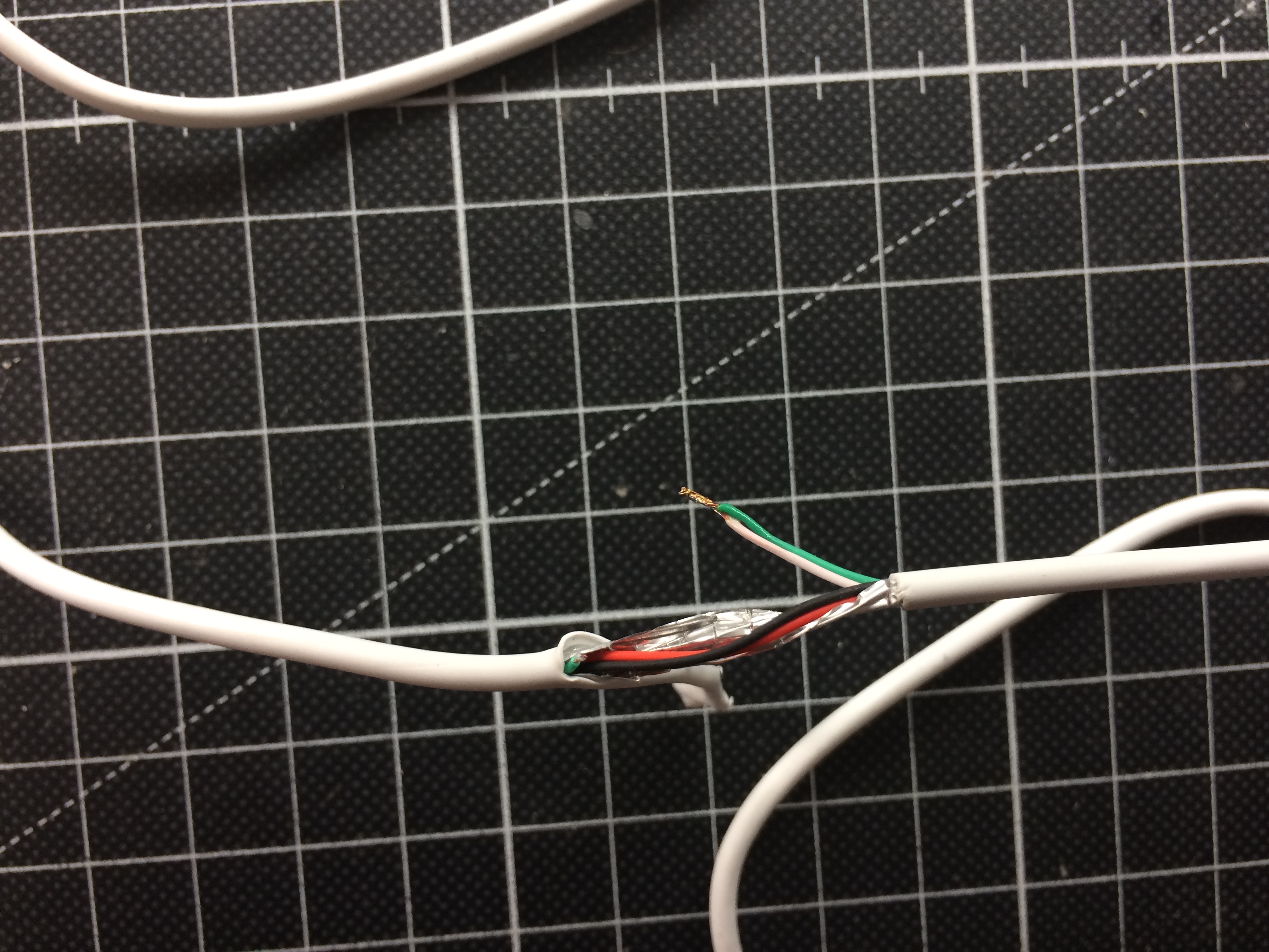
The second way is what I'm making possible by modding a cable, connecting D+ and D- on the device side.
Cue the montage
Cut cable open, solder wires together
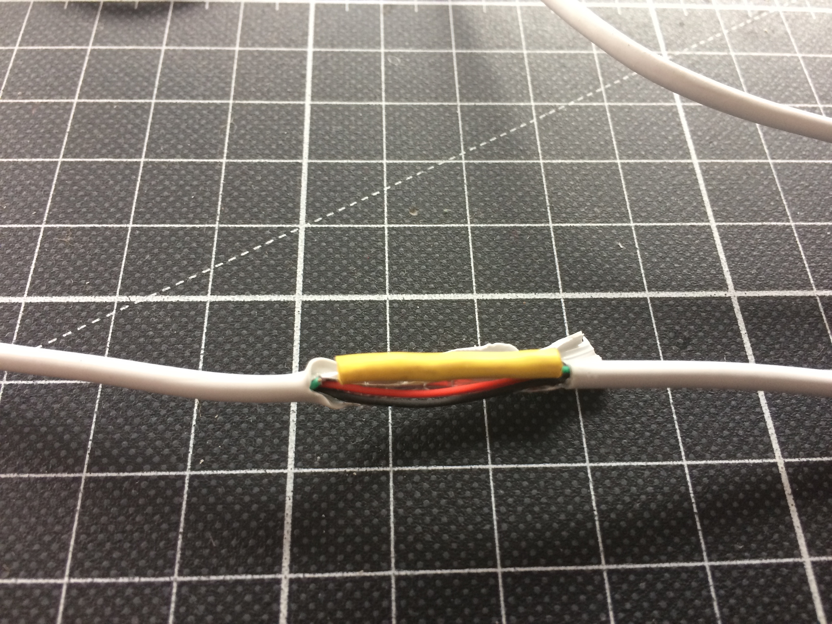
Heatshrink it
Make your mama proud with quality craftsmanship

Tape it
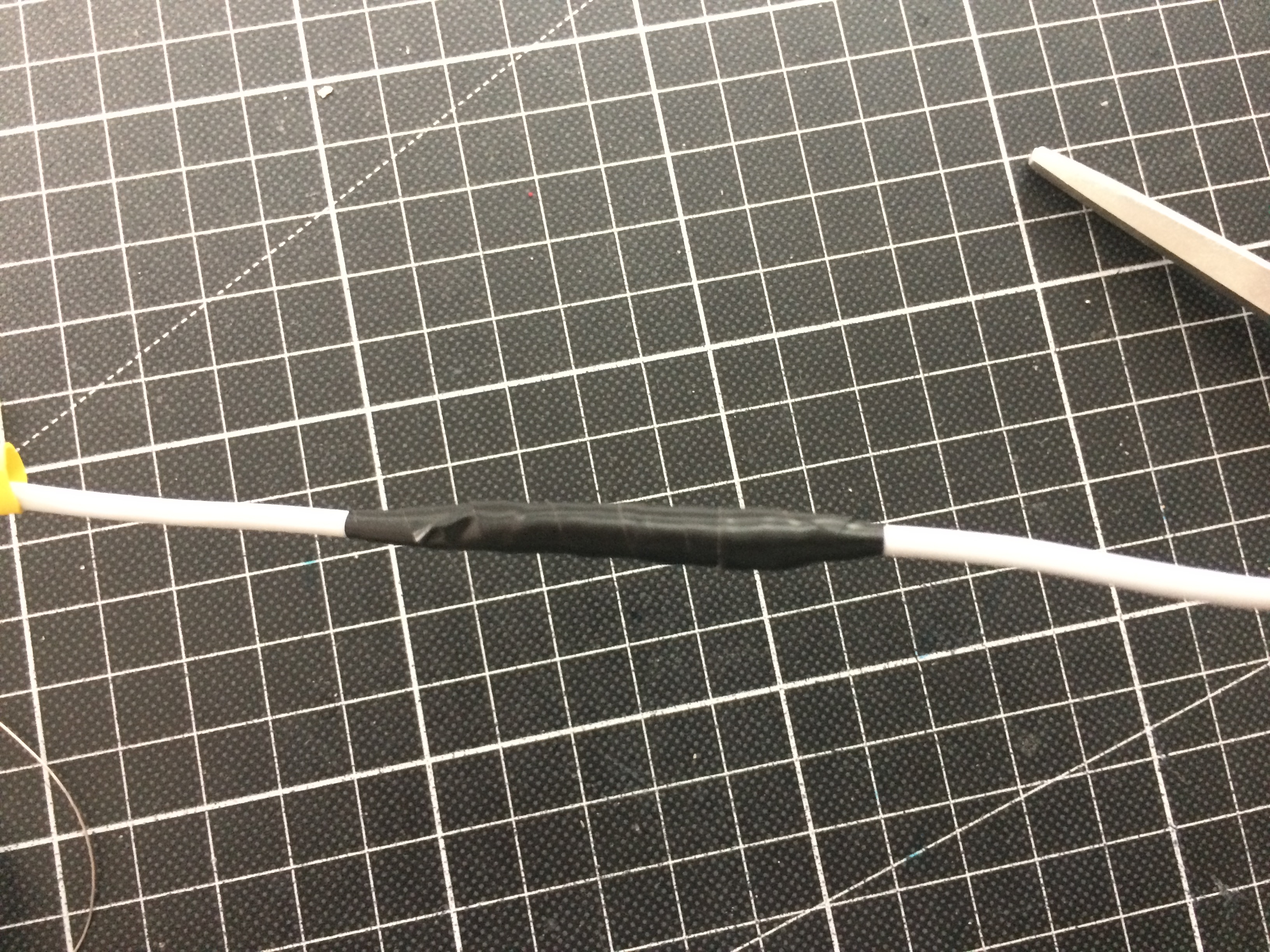
And it works perfectly. The iPhone thinks it's connected to a cheap charger, the USB hub will just have to handle the power draw that it doesn't know about, and everyone lived happily ever after.
I'm doing some completely unrelated internal MIDI mods to some other gear and I just wanted to say that this is an inspiration. Curious to see how it's working now!
This looks smaller and cheaper: Hobbytronics USB Host than the above host board but is only available as an SMD kit.. a bit beyond my through-hole expertise.
Thank you so much!
So actually, it's not working right now but I haven't had time to troubleshoot yet. The power distribution works fine, no problem, but somehow MIDI is not passed through. I suspect there's a problem with the signal quality somewhere, but as I said, no time to troubleshoot. (And it's still working fine with my Keystep, I just have an additional cable to connect)
Yeah, there's a few USB MIDI Hosts like that, but for me an important feature was to still be able to connect the deluge to my PC or my iPad. Neither of those devices can act as a MIDI device, they are always hosts.
Troubleshooting Update
Finally I had time to troubleshoot the whole USB connectivity thing! As it turns out, the RK 005 is at fault. It seems to have a little quirk: If anything is plugged into the USB-HOST port while it's booting, it won't detect any devices. At all. So, I don't know why it did work for a short while, but I know why it doesn't work now.
I wrote to Retrokit, maybe there's a software fix for this, but my hopes aren't too high.
So, the other (and probably better) solution is to build a Power Management Unit. Its purpose would be to control which parts of the system get power and when. Ideally, it would also be able to detect whether USB power is plugged in or not and decide whether to charge the batteries, so it could solve that problem as well. I'm imagining a small Arduino, pin headers and some power transistors on a perfboard. I'll draw up a schematic in due time.
Hi there @iFreilicht
I've recently bought a Deluge, and I'm fascinated with your mod!
Will be following your progress to see if I'd be able to do similar to mine.
Thank you for sharing your experiences!
Your experiments are very helpful to give insight.
Best regards, please keep us updated!
Would be really cool if I can get it to a stage where all the 3D-Files, schematics and so on are available so anyone can replicate it.
I got a update from Retrokits, btw: They say that this is a very common issue, but nothing they can fix.
They also recommended I try a downgrade to older versions, but that didn't change anything. So I'll go with my safer approach.
Little update
I actually finished a prototype for this, and it works pretty well. You can see that I had to use 5 of the available 6 pins on the ATTiny, so there's no way of reprogramming it while it's inside the Deluge. Not to worry, though.
Quick walkthrough:
So here's a short rundown of what happens:
If there's no power, nothing is running (of course).

Once USB power is connected, the CHARGE MOSFET turns on. This is just done with a pull-up resistor, the digispark isn't even powered yet.
If the power switch is flipped (simulated by this jumper wire), the digispark is powered by the battery. And immediately turns charging off. This is important, otherwise the powerbank would shut down as it does not support charging and discharging at the same time.
It also turns power to the RK-005 (simulated by the green LED) on, either using the USB_MAIN or BAT_MAIN MOSFET, depending on whether USB is connected or not.
And after a delay of a few seconds, the INT_5V MOSFET is turned on as well, providing power to the USB Hub and thus the Deluge and all connected devices (simulated by the yellow LED).
Slight caveat
This doesn't actually work with real components. The problem is that I didn't really know how MOSFETS work, so I just bought N-channel ones because they are more common.
HOWEVER, as I now learned, N-channel MOSFETs can only switch loads properly at the ground side! For turning the high side on and off, you have to use P-channel MOSFETs. Now it would potentially be possible to redesign the circuit to only switch on the low side. However, I don't feel comfortable doing this. I'm not an electrical engineer, but from what I know this would be incredibly unsafe in this case, as it would mean isolating the different grounds of the different devices from one another, which could lead to all sort of weird issues with charge building up on the different grounds. I could see ESD problems arising or even weird current spikes when plugging the whole thing into a USB port, resulting in damage to the hardware or whatever it's being plugged into.
So, I gotta make a trip soon and get my hands on some P-channel MOSFETS. Also get thicker wires for the power distribution. Surely there's not gonna be a single problem after that")
@iFreilicht said:
>
Try a solid state relay?
https://www.newark.com/vishay/lh1512bb/dip-8-ssr-dual-1-form-a-b-c-e3/dp/27AC7285?mckv=sASXvnTF6_dc|pcrid||plid||kword||match||slid||product|27AC7285|pgrid|1231453065150502|ptaid|pla-4580565447748066|&msclkid=89cde86fcb611bde3044b6bff67489f8&CMP=KNC-BUSA-GEN-SHOPPING-Test97-Switches-Relays-Relays>
Wow, this hacking project is amazing! How did it end? Were you able to overcome all the difficulties? 😊
Thank you so much! It didn't end yet. I just didn't have much time to work on it. More on the difficulties below.
I actually implemented a simpler alternative.
What didn't work
The PMU circuit
So I did get P-channel MOSFETs and re-did the whole circuit with them, but even then I had very strange issues. Sometimes, they'd latch even though I pulled their inputs low, sometimes they would somehow trigger each other, it was a mess.
I think the biggest problem were currents flowing in ways through the microcontroller that I did not anticipate and still don't understand. So we'll have to go with something simpler.
The USB Hub
I also tried to get a more reliable connection to the USB hub by modding it to a pin header. This worked great for the port for the Deluge, I just had to bend the pins a little bit to fit the non-uniform spacing of the USB-A ports:
But on the USB hub, this was very hard as it has a mini-USB connector. I did get it to kind-of work:
There was no short between the two lines and it worked when connected to my PC, but as you can imagine, the whole thing wasn't very riggid, and while debugging, plugging stuff out and in, I accidentally ripped the pin header from the board, together with the pads.
I actually tried to fix that again by connecting directly to the hub controller, but connecting that to my PC actually gave me a bluescreen, likely due to the mismatched line length and horrible interference, so I gave up on that front.
So I would pretty much consider the hub to be broken at this point.
Where to go from here?
This was all incredibly frustrating, it felt like it just made steps back, none forward.
So I stepped away for a while and then tried to have a fresh look at what I wanted to achieve.
All I want for now is to have the RK005 connect to some USB devices and the deluge and to have all that powered by the powerbank.
And this is the most simple solution I could come up with that makes this work:
So there's three main changes here:
This way, I have to solve less problems at once and can just concentrate on getting the minimal viable solution working. Once that's done, we can work on upgrades.
I actually worked on part of this already, and I will write about that as well, but for today I'll end here. It's late and I'm tired")
555 delayed power circuit
Alright, so the thing I did actually accomplish is the 555 circuit. This makes it so the RK005 gets power 3 seconds after all other devices. In my testing, this seemed to be a reliable way of making it detect all connected devices reliably. I'm not sure why, but as long as it works, I'm not complaining.
So, I prototyped on a breadboard first and then put it all on beautiful perfboard:
This is the PCB where all grounds from all devices come together as well. This should help prevent ground loops which can lead to noise on the audio channels.
Luckily, the holes on the perfboard are spaced in such a way that I only had to drill them out a little bit to screw it to the mounting holes I initially intended to use for a Raspberry Pi Zero W. So this is what it looks like now:
As you can see, the RK005 isn't connected yet. I did make the cable already., but it would only pull power without doing anything.
Next up: redesigning the internal mounting piece
So to mount the USB-C connectors, I'll have to modify the 3D-printed mounting piece, and I'm using the opportunity to split it up into multiple parts to make it easier to print. The overhang from the first iteration turned out awful, so I'll split that part off.
I'll also split off the part the RK005 and 555 circuit are mounted to. This part should be interchangeable as I already have ideas how to replace the RK005 to get even more functionality from the hub. This is roughly what I'm thinking about:
That's it for today. I hope I'll be able to continue working on this at a steady pace. Have a good one!
This is awesome to see. You've inspired me to start framing out a variation on this mod utilizing the Deluge's ability to itself act as a USB MIDI host as of v3.
I'm thinking I can maybe even do this without having to desolder or impact the functionality of the USB port or the 9v barrel jack. By using 3S battery management boards instead of a powerbank & then some DC buck converters to get a stable 5V & 9V DC voltage from the pack, I should be able to effectively "plug in" the deluge with a DPDT slider switch & then tap off the barrel jack to charge the pack, as well.
Since the pack will have a disconnect, the deluge will still be running off it's original internal battery, and would charge itself from the reserve pack. The hub would receive 5V directly from a separate 5V regulator (looking for a hub that'll accept ~5v2.5A on a barrel jack or something & output >500mA per port such that i don't need to hijack the USB 5v pins)
Here's the latest complete diagram I made, I think I'll definitely need a relay or something to prevent from backfeeding the output of the 9v buck converter when in charging mode but overall I think the plan feels solid. I'd also like to engineer a 9V cutoff circuit for the batteries to prevent overdischarge. There doesn't seem to be any off-the-shelf boards for this. I also wanna install a display along the bottom edge to reflect battery charge status.
Lemme know if y'all have any suggestions or criticisms. Definitely pushing a bit outside my comfort zone with this mod but the premise of powered USB ports on this machine is too good to pass up. The gooseneck light sold me.
EDIT replaced diagram w/ a slightly newer one, this time with DPDT switches on both input & output to switch between charge//discharge modes (in actuality these will both be DPDT relays, controlled by a single DPDT ON-OFF-ON switch
Inspired by this post - I made an own simplified version of this..

